
The Radio-Stack inside a C172p
The Radio-Stack inside a C172p
|
 |
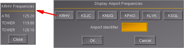
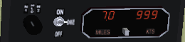
The rotary-switch at the left side connects the microphone with the transmitter wanted. Below that there are the 3 lights with special meanings during the final approach:
|
 We will fly to that "green NDB" directly north of us
(360°):
We will fly to that "green NDB" directly north of us
(360°): 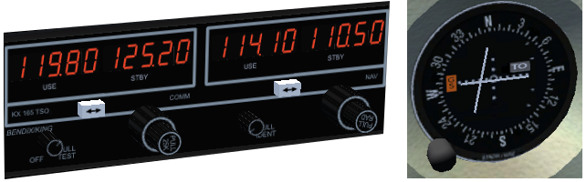
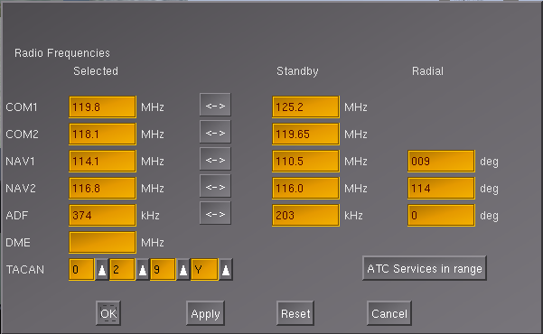
| Selected / Active | Standby
/ Preselected |
Remarks: |
|
| COM1
|
KRHV-TWR |
KRHV-ATIS |
|
| COM2
|
KLVK-TWR |
KLVK-ATIS |
|
| NAV1
|
VOR SJC
(+radial 009) |
KLVK ILS 25R
|
only NAV1 can be used for VOR- and ILS-approaches when using
the Autopilot!! |
| NAV2
|
VOR-OAK
(+radial 114) |
VOR-ECA (R=229) |
the radial "229" for the VOR-ECA must be set later, when that
VOR gets switched to "selected"! |
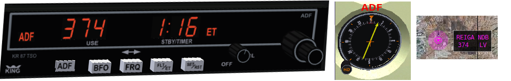
| ADF
|
KLVK – acronym title="Initial Approach Fix">IAF
REIGA |
Reference
TRACY |
See the chapter "IFR approach" |
| DME
|
In the very
rare case of a DME, that is not integrated into a VOR |
In the newest FlightGear Releases there may also be a
Transponder-field to be used with VATSIM. That one then should be set
to 7000 for VFR - otherwise as advised by
ATC |
|
| TACAN
|
here set for
the Carrier "Eisenhauer", at Marseille (France) |
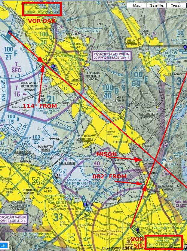 |
In the graphic on the left
you
see 2 VORs, named "OAK"
and "SJC".
Let us analyze line by line what a typical aeronautical chart tells us
about e.g. the "VOR
SJC" (see it outlined
in the right lower corner):
1. "114° FROM" coming from the
VOR OAK
2. "002° FROM" coming from VOR SJC Those two radials happen to meet somewhere, and this unique meeting point is given a special name: "MISON". Thus it is a very important "FIX"-point in the Bay-Area! Such a FIX is not seen during strict VFR-navigation, because it is just a crossing of two radio-signals - so do not try any sightseeing for it! By defining such FIXes traffic can be routed not just by defining VORs as way-points, but also by the crossing of two radials. Those FIXes are very often used as "waypoints" in Flight-plans, as Reporting-Points for ATC, etc. |
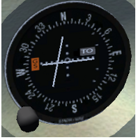 OBS =
"Omni Bearing Selector": When you rotate the knob at the lower left
corner, the wind-rose-scale inside
the
instrument will rotate too - placing the currently selected radial at the very top
of
the scale: See e.g. the value "N" (= 000° or 360°) in the picture. With
this setting you fly with a heading of 360° "TO" (=North) or "FROM" (=South) the
VOR-transmitter. OBS =
"Omni Bearing Selector": When you rotate the knob at the lower left
corner, the wind-rose-scale inside
the
instrument will rotate too - placing the currently selected radial at the very top
of
the scale: See e.g. the value "N" (= 000° or 360°) in the picture. With
this setting you fly with a heading of 360° "TO" (=North) or "FROM" (=South) the
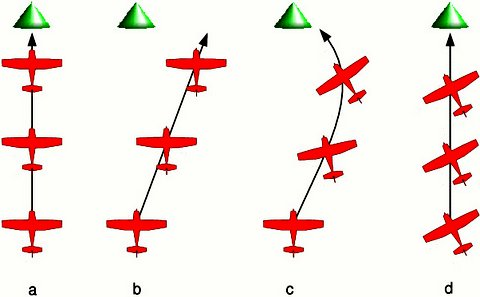
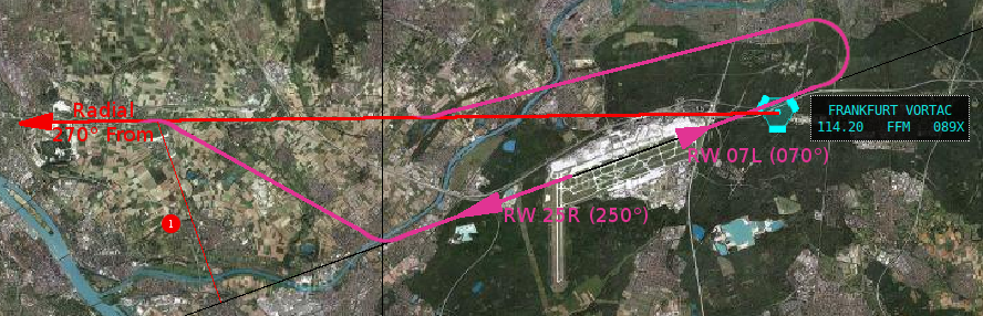
VOR-transmitter. CDI = "Course Deviation Indicator": This is the vertical needle inside the VOR-display. If that needle is vertically centered, it tells you that you are on the selected radial - if not, it indicates into which direction you have to correct your heading in order to return to the radial. GS = "Glide Slope": The horizontal needle in the instrument functions like the CDI, but in the vertical direction! Watch it: A "Glide-Slope" is only available from some ILS transmitters, and its signal usually reaches only 10 nm out from the "Touch down Area" of the runway. The GS becomes active a long time later then the CDI - which is active already 50 mi out and more! TO/FROM: Do you see that little cutout at the right side of the center, now indicating "TO"? In that window will appear a "TO" when the radial brings you towards the VOR - otherwise it will show a FROM (or short "FR"). If neither "TO" nor "FR" is indicated you are not inside a valid range to a VOR with that frequency! To make it very clear: The "TO/FROM" indication does NOT indicate in what direction you actually fly - it just tells you in what direction the radial points - so yes: Although when flying on a radial "FR 270" and a centered CDI you may very well be flying towards the VOR! But in case you deviate from the radial, the CDI will indicate the needed correction reverse! Have a look at all 4 possibilities and there effects: 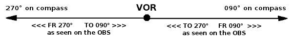
|
 The HSI is a combination of the OBI and the Heading indicator. The HSI is a combination of the OBI and the Heading indicator.It is somewhat more expensive - and thus not in our c172p! If you want to know more about it see: http://en.wikipedia.org/wiki/Horizontal_situation_indicator |
| The Compass and/or
ADF show where your nose points to the VOR/ILS shows the course!! and helps you to stay on course, even when not using an autopilot !!!!! |
 |
Specifies a VOR without DME |
 |
Specifies a DME without VOR |
 |
Specifies a combined VOR-DME, for both functions you need to set only the VOR frequency (the unique DME -frequency will be set automatically!) |
 |
Specifies a TACAN (= a military VOR), those always include a DME, but no VOR for civil usage! |
 |
Specifies a VORTAC, the all-in-one solution: It combines the civil VOR-DME + the military TACAN! It does have different frequencies for military and civil usage, and both set the unique DME-frequency automatically |
|
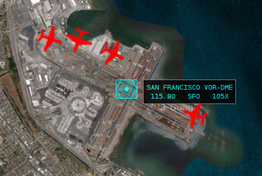 |
In KSFO you see the example of an "ideal " setup: There is a VOR-DME
in the center of the Airport. So here you can use the VOR as support
to get you onto the ILS-localizer, and have a pretty exact distance
measurement as well for the VOR as the for the ILS and or Glideslope! So you can use the your
|
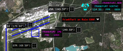 |
In EDDf it is just a little more
challenging. There also is a VOR - but a little outside, which is still
good enough for aerial-navigation. But see the symbol - it does not have
a DME! But there is a standalone DME in the center of the airport. (For
that one is shown in FGFS only the military frequency. If you look into
other (newer) navigational maps you see it has a distinct civil frequency of
115.9 MHz (see e.g. http://www.ourairports.com/navaids/FRD/Frankfurt_DME_DE/). That means you need to set 3 frequencies: 1) Set the VOR 114.2 into NAV2 2) Set the DME 115.9 into NAV1 3) Set the DME-Selector first to "1" to get the DME 119.5 indicated in the DME-display
4) Set the ILS-frequency into NAV1then switch to "HOLD" --> that holds the DME, even when changing the NAV-frequency |
|
So never forget: You are the Pilot in Command -- not the
Autopilot!! |
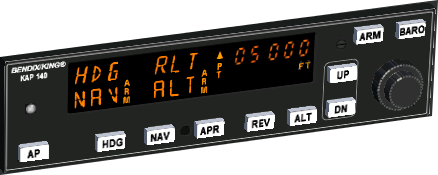
| actual
(cursing) altitude |
actual
"preset" altitude |
set UP/DN |
Action |
| 3000 |
4000 |
(+) 500 |
we will
climb to 4000 ft with a rate of 500 fpm |
| 3000 |
4000 |
-500 |
we will
descent to crash
with a rate of -500 fpm |
|
2000 |
(+) 500 |
we will
climb until crash
with 500 fpm (or land on the moon) |
| 3000 |
2000 |
-500 | we will
descent to 2000 ft with -500 fpm |
| 3000 |
3000 |
(+)
500 then -500 |
"jump"
over an obstacle and then return to the set altitude |
 |
These Approach-charts are not
really standardized worldwide - but they all contain some common
informations: (Sorry. usually those
are not as nicely colored as seen here!)
There are usually a lot more informations at changing locations on the charts. e.g.: There may be "minimum values" for an approach, e.g.
|
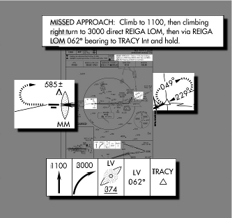 Parts of that procedure are shown in several places on the
IAP: Parts of that procedure are shown in several places on the
IAP:
1. Climb straight ahead to 1100 feet 2. Make a climbing right turn to 3000 feet 3. Fly to REIGA (compare the frequency and Morse-code!) 4. Fly outbound from REIGA at 062◦ 5. Fly a holding pattern at the TRACY intersection The holding pattern, as you might have guessed, is a place where you can “park” while sorting things out, and has its own set of procedures and techniques which we won’t go into here, because . . . (but have a look into the chapter "Procedure-Turns" in the part "KnowHow".) |
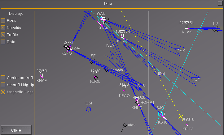 |
You (the yellow plane symbol in the lower right)
just started at KRHV,
now flying on
runway-heading 310° towards the "airway 334", which follows the
(cyan)
Radial "SJC 009",
which we have set before into our NAV-1, and which we will intercept
soon. The next check will be the crossing of the radials "SJC 009" and "OAK 114" (which is set in NAV-2) near the fix "SUNOL", which is not marked here by name, because the "Fixes" are not activated (see in the upper left corner!)! But because "Navaids" are activated you see » the VORs "OAK" and "SJC" in cyan,
because they are active in your 2 NAV-radios
» e.g. in the lower left quadrant
you see another VOR "OSI" not in cyan
and without Radial, because we do not use it.
"LV" (in the right upper corner)
is the identifier for the NDB "REIGA", which is
the IAF
for our planned approach to KLVK.
Because "Traffic" is activated, you see the Multiplayers flying in your area. See e.g. "alex" to the left of you and "Godwin" on the dark blue ILS towards KSFO. You should also notice the pointers at those targets: » "alex" is flying
in direction SW and is relatively fast
» compared to "Godwin", who is
relatively slow on Final to "KSFO runway 28"
|
 |
In this picture we changed
already the NAV-2 from "OAK 114" to "ECA 229", and
are on our way from Fix "SUNOL" to the
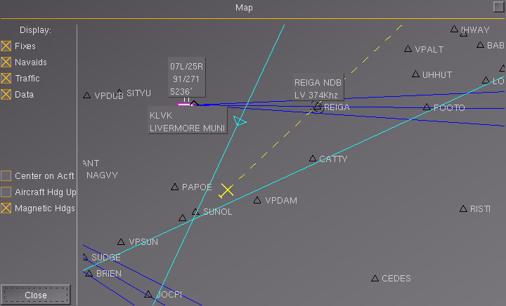
NDB "REIGA". The two radials cross at fix "SUNOL" - this time its name is visible because "Fixes" is now activated. Also activated is "Data", thus we see additional descriptions to the major navigational aids. See e.g. » KLVK with the
runways "07L/25R" that are 5236 ft long. The magnetic headings are
91°/271°
» REIGA with the identifier/morse-code "LV" and frequency 374 Khz See also the Fix's "FOOTO" to which we will turn over "REIGA" on heading 75°. And also notice that this segment of way is directly against the traffic on the ILS towards KLVK - so we better keep a safe altitude. |
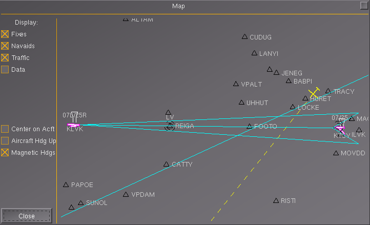 |
In the above we headed for
"REIGA". In the meantime » we turned to a hdg of 075° over
"REIGA"
towards "FOOTO"
» which is defined by our course
of 075° and the crossing radial "ECA 229"
» there we turned to 030° » and after 2 Min. we turned 180° to a new heading of 210°, back towards the ILS-Localizer REIGA On this heading 210° we are now going to intersect the ILS 25R of KLVK. Did you notice that that ILS is now in color "cyan"? And the radial "SJC 009" is not shown any more! Sure: We do not need the "SJC 009" any more and thus switched the NAV1 to the "ILS 25R"!
Also notice that we are close to "TRACY" - the
other "IAF" (Initial Approach Fix),
and thus very close to the 10 nm radius, that we were not allowed to
exceed!
|